Introduction
This article describes how to use a MicroStation CONNECT Report to export DGN linear element coordinates and other information. By 'linear' we mean DGN line elements and line-string elements.
Reports
MicroStation CONNECT introduced Reports. Reports is an analytic tool. It extracts alphanumeric data (DGN or business data) from your DGN file, model, elements or elsewhere. When Item Types are in use, Reports can extract Item instance data attached to your DGN model or elements.
Visit our reports page for more information, and to see other examples of Reports in action. Don't forget to visit MicroStation's Reports help documentation.
XYZ Text Tool
For some time, MicroStation has had an XYZ Text tool. That tool's purpose is to let you create a CSV file containing a list of coordinates. However, the tool is restricted to text and point (cell) elements. Here, we show you how to define a Report that harvests linear element data.
Post questions about Reports to the Be Communities MicroStation Forum.
Define a Linear Report
In a few simple steps, we'll define a MicroStation Report that will write a CSV or Excel file. The file will contain multiple lines of data. Each line will contain the line coordinate data and other information.
Create a New Report Definition
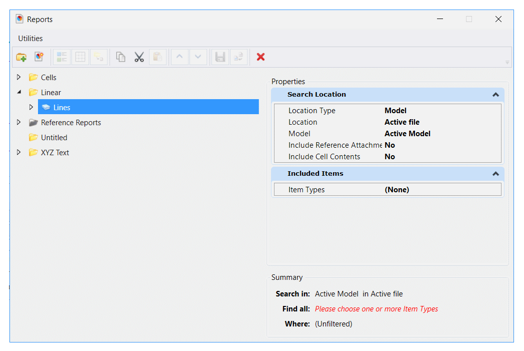
In this example, we want to export line vertex coordinates. The Report category is named Linear. The Report definition is named Lines …
Add Linear Elements
This is where the user interface is confusing. We want to report information about line elements, which are a type of DGN element. The Report definition form is asking for a Search Location and Included Items. Leaving Search Location as it is (collect information from the active model in the active file), focus on Included Items.
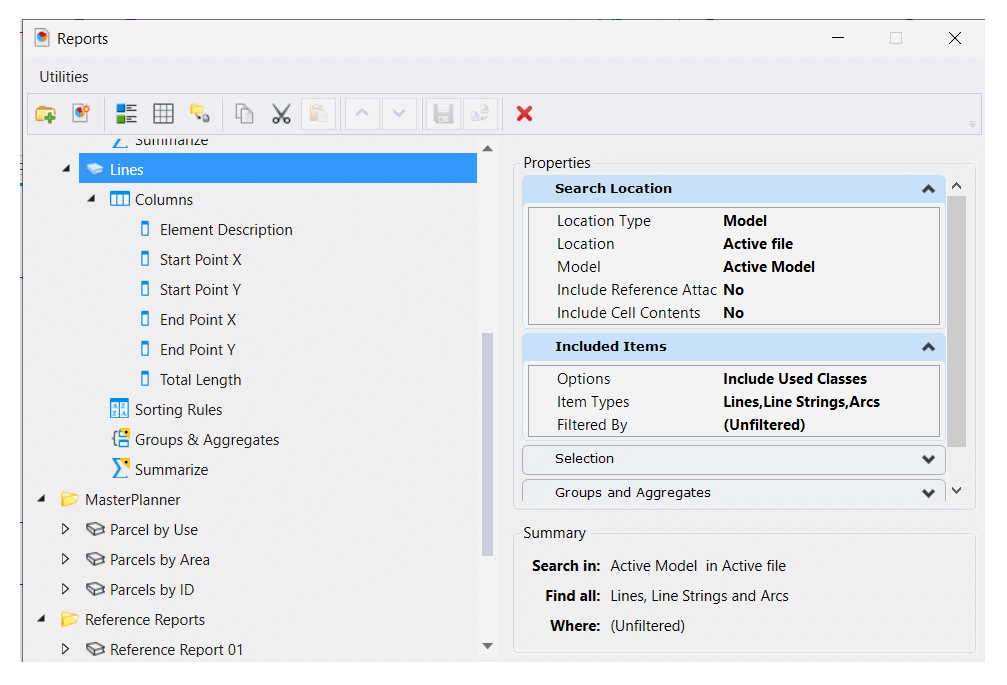
From MicroStation CONNECT Update 15, the Included Items pane has an Options option button that lets you choose Include All Classes or Include Used Classes.

If using a version of MicroStation earlier than Update 15, that option does not appear. You must place at least one instance of a cell in the active DGN model to continue defining your report.
The form seems to be asking you for an Item Type. If you click that option, you are taken to a new anonymous form having an option button Include these Item Types. Don't give up! Click that button to find that you can also choose DGN Elements. Expand that option to see a list that may contain Lines. I write 'may contain' because that option won't show if there are no line elements in your DGN model! Click Lines and Line Strings to add those Item Types to your Report …
Add Columns to the Report
Right-click the Report definition and choose Add Columns …
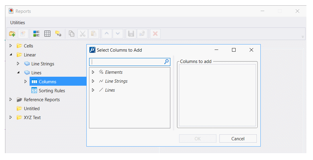
Here we've added a column named Element Description that describes the DGN element and other information specific to lines …
Format the Coordinate Column(s)
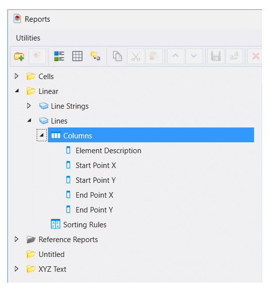
MicroStation, by default, formats the Start and End columns by merging their X, Y and Z values into one string. That may be inconvenient if you want to analyse individual coordinate values in some external application, such as Excel. We're going to apply formatting to the Start and End coordinates to separate the X, Y and Z components. First, copy the Start twice. Then, rename each column to Start X, Start Y and Start Z. Do the same for the End column …
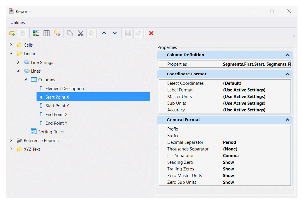
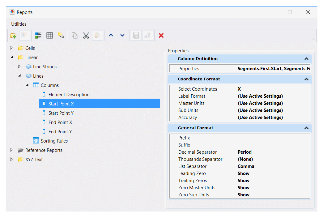
Now, right-click each Start and End column in turn and choose Add Formatting. In the Coordinate Format pane, choose Select Coordinates …
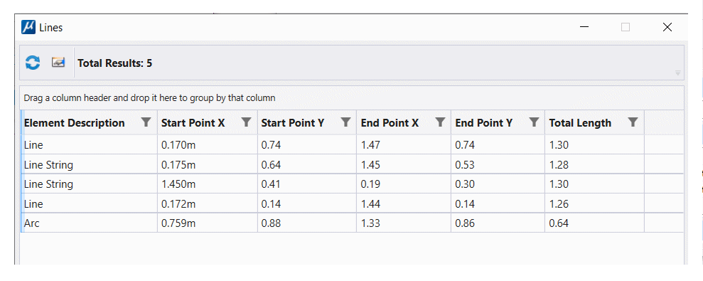
Your Linear Report is ready! Click the Preview Results button …
More Columns
Your Report definition is adaptable. As shown above, you can add a Element Description column to the Report, and the number of segments (No. Segments) that make up each line, and its Total Length …
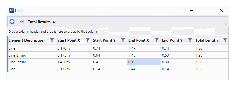
The above Report harvests the start and end points of each line or line-string. For a simple line, those are the only points available. However, if you want to get the value of each vertex in a line-string element then you must request the Segments.All property. Now you can get the start and end points of each segment that constitutes the line-string …

Export Formats
Send your Linear Report to a CSV file …
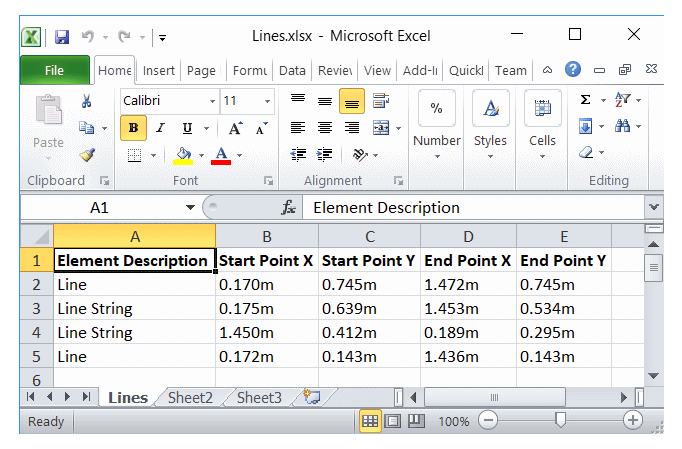
Element Description,Start Point X,Start Point Y,End Point X,End Point Y
Line,0.170m,0.745m,1.472m,0.745m
Line String,0.175m,0.639m,1.453m,0.534m
Line String,1.450m,0.412m,0.189m,0.295m
Line,0.172m,0.143m,1.436m,0.143m
…or to an Excel file …
Additional Formatting
Krister Surell, an enthusiastic contributor to Be Communities, commented: there are tweaks you may like to make to your export presentation. When defining your Report, click on a coordinate column to see a Format pane on the right.
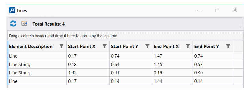
As shown in the CSV report above, the coordinate data is written by default using MicroStation's master units label as the suffix (in this example,
m for meters). The decimal precision is the default three decimal places.
You can write an undecorated value by choosing Label Format MU instead of Use Active Settings.
You can adjust the number of decimal places using the Accuracy option.
Here's the CSV result when we omit the units label and reduce decimal precision to two …
Element Description,Level,Total Length,Start Point X,Start Point Y,End Point X,End Point Y,No. Segments
Line,Lines,1.303m,0.17,0.74,1.47,0.74,1
Line String,Lines 2,1.285m,0.18,0.64,1.45,0.53,2
Line String,Lines 2,1.297m,1.45,0.41,0.19,0.30,3
Line,Lines 2,1.264m,0.17,0.14,1.44,0.14,1
Example DGNLib
Design Library file ReportExamples.dgnLib contains the Report definition described here.
It is available, along with a sample CSV file and Excel file.
More information here.
Contributors
I am indebted to Bentley Systems staff member David Trejo-Rodriguez who posted the original hint on which this article is based, and also to Krister Surell, an independent developer at surell consulting ab. They both contribute regularly to the MicroStation Forum.
Questions
Post questions about MicroStation tools to the MicroStation Forum.